Engine rebuild project

For Type 3 and 4 restoration projects, interesting history, adventure trips etc
haz
Posts: 168
Joined: 21st September 2009 - 12:47am
Location: Central South Island NZ

Re: Engine rebuild project

Post by haz » 16th October 2013 - 2:52am

Still struggling with the full flow conversion, cant decide whether to use a pump adaptor plate & "Clearance" the fan housing & support bar or to go for a casing conversion by welding ports onto the oil ways or even using 90' hydraulic fittings as Broadly suggested,

Image

Does anyone know what the oil pressure & flow rate is from a stock pump so I can suss out what banjo fittings might work for this?

Image

Anyone got any details of the "clearancing" required for the adaptor plates?

User avatar
jmarkha1
Posts: 563
Joined: 25th July 2006 - 9:02pm
Location: Surrey

Re: Engine rebuild project

Post by jmarkha1 » 16th October 2013 - 8:23am

I would not use the upper oil way near the distributor drive - looks prone to cracking.
How about using a full flow oil pump cover outlet and use one of the CSP inlets at the pressure relief underneath engine - if you go to csp.de you will find the fitting - looks good for type 3s and reduces the need to grind the fan.
http://csplink.de/ptsNNJbxeL
The variant Project

haz
Posts: 168
Joined: 21st September 2009 - 12:47am
Location: Central South Island NZ

Re: Engine rebuild project

Post by haz » 17th October 2013 - 1:23am

Good point, on looking at my lump while the upper port is just as wide etc the stud would need to be quiet small in dia & short due to how close the dist opening comes to the oil way.

Image

Only thing with the Csp part is the need for external oil cooling, is this a simple conversion to do on a type3?

User avatar
jmarkha1
Posts: 563
Joined: 25th July 2006 - 9:02pm
Location: Surrey

Re: Engine rebuild project

Post by jmarkha1 » 17th October 2013 - 7:59am

very simple with external inline wax thermostat from mocal and one of their 16 row aluminum oil coolers.
Not the cheapest option but does give reliable cooling with balanced cylinder cooling (no cooler on motor).
lots of opinions on this - cheaper option is definitely tap the case on the side oil passage and oil pump cover.
The variant Project

haz
Posts: 168
Joined: 21st September 2009 - 12:47am
Location: Central South Island NZ

Re: Engine rebuild project

Post by haz » 17th October 2013 - 8:50am

to be honest & within reason, Im looking for the simplest & most modification free option not just the cheapest.

Will look into how to do an external cooler conversion, if it gives a better temp control & is an improvement in its own right as well as just the filtration up grade then I would consider it.

When you say "grind the fan" you do mean the fan housing yeah not the actual fan?!!

User avatar
jmarkha1
Posts: 563
Joined: 25th July 2006 - 9:02pm
Location: Surrey

Re: Engine rebuild project

Post by jmarkha1 » 17th October 2013 - 9:00pm

External stat and cooler is straightforward to plumb in and with an electric fan (stat or manually switched) gives you a lot of control.
Grind the fan - yes clearancing the housing and support bar - not the actual fan.
Mocal sells everything you need apart from the oil pump cover, the CSP inlet union and stock oil cooler block off plate with temp sender- you can use 1/2 BSP fittings on stat, cooler and case connections that will not leak and give you trouble free
The variant Project

User avatar
broady_6
Posts: 2912
Joined: 13th January 2009 - 8:55pm

Re: Engine rebuild project

Post by broady_6 » 17th November 2013 - 10:40pm

sorry I havent posted, thats my engine youve got a photo of there. have you decided which route your going?
The sultan of swing

haz
Posts: 168
Joined: 21st September 2009 - 12:47am
Location: Central South Island NZ

Re: Engine rebuild project

Post by haz » 25th November 2013 - 6:31pm

Been shown a conversion done by a local garage here and think I'll take mine in to them once Im assembled to that stage,

Image
Image

Having found out that we are expecting our first child (planned), things have been a bit on the back foot with this so its now more of a "hope to be ready for the nationals" project than a winter rebuild :lol:

About the only thing that this recent news has changed is that in order to stick to the 1776 plan I will have to import as much as possible myself to keep the costs down but think there's enough in the coffers to still go ahead with it.

Toady, for the first day in a long long time I got stuck in again, pretty much finished the strip down now, just need to get the parts into work next weekend & start cleaning up in there parts bath. A few scary looking findings in the case, on the goo side though it still has the VW stamps so cant have been bored or bushed before. Looks like I got there just in time though,,

Image
Image
Image
Image
Image

The crank journals are clean & the cam is being replaced but also looks to be ok.

On another note, I cant get the last dowel nearest the oil pump out with pliers, any idea, heating maybe?

haz
Posts: 168
Joined: 21st September 2009 - 12:47am
Location: Central South Island NZ

Re: Engine rebuild project

Post by haz » 4th December 2013 - 8:36pm

Nudge,,

Any ideas on the stuck dowel?, pliers or mole / vice grips wont get it, should I / could I leave it for the machine shop?

Cheers.

User avatar
jmarkha1
Posts: 563
Joined: 25th July 2006 - 9:02pm
Location: Surrey

Re: Engine rebuild project

Post by jmarkha1 » 4th December 2013 - 9:04pm

heat will not help - why not leave it there unless you are going for a line bore.
If you are - leave it for the machine shop to remove.
The variant Project

User avatar
broady_6
Posts: 2912
Joined: 13th January 2009 - 8:55pm

Re: Engine rebuild project

Post by broady_6 » 7th December 2013 - 9:28am

as said above, if it doesnt need to come out then id leave it be. It probably wont fit as nicely after its been forcibly removed
The sultan of swing

haz
Posts: 168
Joined: 21st September 2009 - 12:47am
Location: Central South Island NZ

Re: Engine rebuild project

Post by haz » 7th December 2013 - 11:15pm

Got it out thanks, used a small pair of water pump pliers.

Spent a couple of hours & a few litres of old petrol washing 42years of grime away,

Image

Image

Also, for anyone thinking "dont know if I want to bother with a full flow conversion for their rebuild, just like I was,,

Image

At least Ive found those bits that broke off of the bearings, just need to srape them off & glue them back on with some No nails & should be able to reuse them :lol:

Image

Not sure if its the first time the engines had any work or not but must be in for its first line bore,

Image

Also managed to pull all the required oil way plugs & flushed them out, actually where quite clean really.

Better start thinking about my shopping list now,,, :D

haz
Posts: 168
Joined: 21st September 2009 - 12:47am
Location: Central South Island NZ

Re: Engine rebuild project

Post by haz » 15th December 2013 - 6:23pm

SCRREEEEECCCH, Stop the wagon, we've hit a bump,,!!

Now I said above I followed the huelsmann way, and now find myself in the tricky what to do with what is known as No4 plug which has a restrictor attached to the back of it limiting oil to No4 bearing assembly.

There’s a lot of input & theory bashing on this out there but I think this is the high & low of it;

Some say that the restrictor is there because the VW engineers knew that after-market bearing makers might not stick to the original 2.3mm oil hole & bigger would both starve No3 bearing & cause oil leaks from the end seal at No4 due to the “lame slinger & poor oil seal set up at the front of the engine”, if so then if you have a 2<2.3mm hole in the bearing this is enough to restrict the flow bearing restricting the flow.

But counter to that others say you have to take into account where all that oil goes after the bearing has used it. The volume coming from the total circumference and width of the bearing is volume that ends up against the slinger and drains out the bottom of the slinger cavity. not having a restriction of volume before the bearing would definitely cause oil to come out the pulley.

Image

So to retro fit this restrictor plug or not is indeed the question,,

Now there is, of course, more than opinion on how best to replace this restriction if you wish to do so;-

1- Use a stepped restrictor,
Image

2- Put a drilled plug down the throat of the supply passage,
Image

3- Fit a piece of aluminium that will fit with a interference fit in the hole in the bearing saddle. cut it to about 20mm in length and drill a 3mm hole in the centre. use a 10mm drill bit and cut a concave surface where the hole is so it won’t push up against the bearing and cut off flow. Push it into the oil gallery. The reason for the concave surface is that the hole in the bearing is about 2mm and it may not line up correctly with the hole that you drilled.
Image

4- Finally a local guy would has since deserted the forum previously said; "I put a 8mm grub screw in that one, tap the hole with a starting tap, only deep enough so the plug tightens on the tapered thread. On the restrictor side of things, I bore the number 4 oil feed to 6.8 and also tap it to 8mm, put the gallery plug in the lathe and drill it with a 1/8th drill bit, Its now the restrictor and its removable for cleaning"

Which I think means he taps & fits a restrictor plug into the bearing journal, just like the pushed in alloy rod method?

Must say im preferring the plug tapped into the journal method over tapping & plugging the throat as that would mean opening up the external plug to one size bigger thus reducing the wall thickness, don’t like the Idea of leaving it out or using a stepped as it worries me that if the centres of the restrictor & the thread for the plug where off then you could possibly end up blocking the outlet hole a bit like a cam lock effect.

If anyone has any experience or input its more than welcome!!

haz
Posts: 168
Joined: 21st September 2009 - 12:47am
Location: Central South Island NZ

Re: Engine rebuild project

Post by haz » 24th May 2014 - 11:19am

Well its winter again so might get on with this!!

To say Ive had my thumb up my arse on this would be an understatement, my whole arm would prob still be on the shy side but time seems to no longer be as freely available since the little fella arrived ,anyway, "moving forward" as they say when you dont want to talk about what might, or might not have been happening before now,,,,

Seriously, we had our first child late feb so that has taken over most free time recently, all going great & bit more settled now so able to get things moving again,

Im going with having lugs welded onto the side of the case for the full flow conversion, just think it makes a better job of it & the welding is almost cheaper than the pump cover & fittings anyway!
Been given a scrap case to hack the required lugs off to make sure the alloy is the same.

Image


Also got the bulk of the parts together,

Image

Image


Dual Empi 34's

Image

And,,, probably my favourite, part since I chose these myself (although decided on them with advice) arrived today,

DRD Racings L3 heads, hand lapped multi angle 35.5 X32mm stainless steel valves, Hi Chrome Valve Seats, Silicone Bronze Valve Guides, single hi rev Valve Springs, Chromoly Keepers & Retainers, 16% increase flow, 14mm x 3/4" plug ports, 55cc chambers, 90.5mm bore.

Image

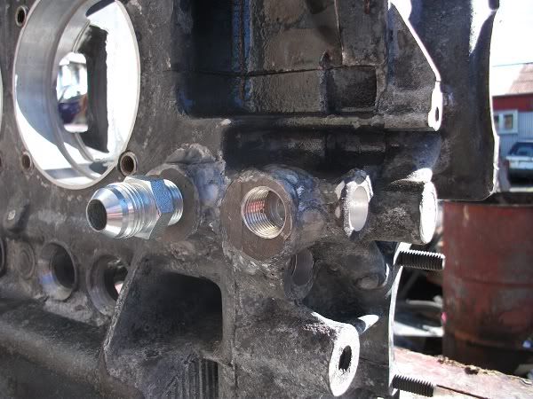
Also Ive got the galley plugs all tapped (other than the 2x 3/8" plugs where I will be getting the side flow ports welded on as that will prob effect the bore so will do those afterwards).

I managed to get one of the 1/8" plugs stuck in the scrap case where I did my test, tightened it a little to much & now the socket is starting to strip, there are more of those than I need anyway, didnt test the ones on my case any where near as tight after that!!

Took it easy with both drilling & tapping, drill a bit, stop clean & check, drill a bit more etc & only tapped 1/4 turn each cut & came out to clean & check every 2 full turns at most, used CRC for both.

Couldn't get the 1/8" plug in the side all the way in as the drill walked a little & created a shoulder in the bottom of the hole, I think once its tight it will be pretty much up to the last full thread though.

Image

Brought a cheap tap set that had a full thread 1/8NPT tap in it & I found that running this down after the interrupted tap removed a considerable amount of metal, and allowed the plugs to sink a bit further in with out going any deeper.

Ive left the 1/8" plug on bore that flows to the oil pressure relief valve a few threads proud as I didn't see the point in drilling all the way through into this bore so I have a left a 2.1mm shoulder, if the fly wheel is to close I will grind the top off the plug.

Image

Also the 2 cam follower locations are slightly proud, (one of them seen at the bottom of the pic) again leaving a shoulder in the port rather than drilling right through to the bore which the follower runs in.

Found with the 1/4" plug between the oil cooler & dizzy that if I sink this flush it will start to block the galley that flows horizontally to this vertical port, its still a good 3/4 in with out tightening so will seal fine.

Image

And I have tapped the dizzy one so that it will be 1-2 threads proud to prevent thinning the wall of the dizzy bore.

Finally, sorted out the No4 plug prob, read earlier posts for details about this, no drama, just drilled right in & sunk a 1/8" plug down past the main bearing oil feed, this plug will be drilled out to 2.4mm (need to double check that size on the samba) to duplicate the original restriction plug. Then drilled & tapped the first part of the bore for a 1/4" plug, which I need to get as I don't have enough.

Image

And finally, Ive measured up the journals on my crank, will be getting the Mshop to check & polish it anyway but thought Id make sure Im not in for any nasty news,,,

Ive not removed my timing gear but heres the rest:

Main bearing journals:

1 (fly wheel) = 54.98<985mm
2 = 54.96<97mm

Con Rod journals :

No3 piston = 54.98<99mm
No4 piston = 54.98mm
No1 piston = 54.97<98mm
No2 piston = 54.97<98mm

This is with the shaft at 18'c and a 50<57mm (0.01mm) mic, zero checked with a 50mm calibration block.

Looks ok, I think(!), did start checking across 3 points but in the end went around pretty much the entire shaft.

haz
Posts: 168
Joined: 21st September 2009 - 12:47am
Location: Central South Island NZ

Re: Engine rebuild project

Post by haz » 9th June 2014 - 12:33pm

Well, more progress,

Made the bosses to be welded on for the side flow oil conversion, for anyone who doesn't follow what im welding ports on for, its actually about the same cost to have the ports welded on as to buy a full flow pump cover & this way uses far less fittings so reduces the flow much less as well as eliminating the need to modify the engine mount bar or the fan housing.

The oil will flow like this;

Image

The bosses in that pic are the first pair I made, from where the engine bolts to the top of the G/box, but decided they where to small so hacked the web area out from between the cylinders and made a second bigger set.

Image

The case is now away to have the bosses welded on, guys confident it wont be a prob to weld,

Beofore I dropped it off I called in to the machine shop & had a show & tell, all looking good, they suggested re-surfacing the case half's, pointed out the "fretting" on the mating surfaces also it reads about 0.003" bow across the centre which surprised the guy as he expected a lot more. Main tunnel measures up ok, as did the cam tunnel, but these will be line bored anyway once the halfs are scimmed, so case looks very much re-usable. They think the crank will need a grind but will crack test first, otherwise all looks do-able.


So that's that, will get the tin wear cleaned & painted etc & should be ready to collect in about 3/4 weeks,, be back on the road & tearing up the back tyres in no time :smoke:

Better get reading up on how to put this thing back together!!

User avatar
kaddy
Posts: 658
Joined: 25th January 2011 - 12:39am

Re: Engine rebuild project

Post by kaddy » 10th June 2014 - 9:24pm

Nice one. I,m about to start a full fasty resto, and maybe the engine too, now that I,ve seen this thread.
Enjoying it so far

haz
Posts: 168
Joined: 21st September 2009 - 12:47am
Location: Central South Island NZ

Re: Engine rebuild project

Post by haz » 10th October 2014 - 7:18pm

Sooo,,

Got the call on Friday, the engine parts are (finally) ready to collect, need to talk to the shop this week and check the details as the wife took the message but wont be able to pick it up til some time the following week.

Also scored an engine stand for 25quid, one of the universal ones but should be pretty easy to mod the brackets or just make new ones for the vw case so picking that up the same trip, looks like I might need to get stuck in to getting it back together, running before 2015?, not sure id bet the house on it but at least it should be somewhere on the horizon!

So a couple of questions people might be able to answer that I have from watching the various YouTube vids on vw engine building, sure there will be more to come,,

1- Should I oil the piston ring set when they go in, seems some say no, others say yes?

2- Should I use cam break in paste or just EAL?, to me puting grinding paste into any engine seems like not a great idea?

3- Should I grind an oil way grove into the cam lifters?

Cheers.

Post Reply